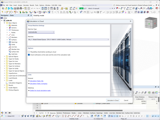
The model and loads are entered as usual in the RFEM interface.
You can start the cloud calculation by selecting an entry in the Calculate menu. Then, select the virtual machine suitable for the task and start the calculation.
After the start, the image is used to create a virtual machine on which the computing server is started. This takes over the calculation of your file.
You can monitor the processing of calculation tasks in the Extranet.

You can import STEP files into RFEM 6. The data is directly converted into the native RFEM model data.
The STEP format represents a standard interface initiated by ISO (ISO 10303). In the geometry description, all shapes relevant for RFEM (line, surface, and solid models) can be integrated by the CAD data models.
Note: This format is not to be confused with DSTV interfaces, which also use the file extension *.stp.

The soil solids that you want to analyze are summarized in soil massifs.
Use the soil samples as a basis for a definition of the respective soil massif. This way, the program allows for user-friendly generation of the massif, including the automatic determination of the layer interfaces from the sample data, as well as the groundwater level and the boundary surface supports.
Soil massifs provide you with the option to specify a target FE mesh size independently of the global setting for the rest of the structure. You can thus consider the various requirements of the building and soil in the entire model.
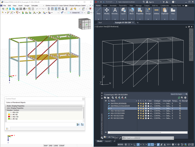
Use the interfaces for more efficient work. You can import your structures in the DXF format as lines from Autodesk AutoCAD into RFEM 6 / RSTAB 9.
Furthermore, you can export different objects (for example, cross-sections) from RFEM 6 / RSTAB 9 to separate layers in Autodesk AutoCAD.
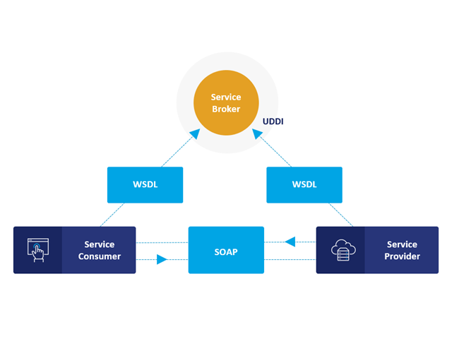
Communication is the key to success. This also applies to a client-server relation. WebService and API provides you with an XML based information exchange system for direct client-server communication. Programs, objects, messages, or documents can be integrated into these systems. For example, a web service protocol of the HTTP type runs for the client-server communication when you are looking for something in the Internet using a search engine.
Now back to Dlubal Software. In our case, the client is your programming environment (.NET, Python, JavaScript) and the service provider is RFEM 6. Client-server communication allows you to send requests to and receive feedback from RFEM, RSTAB, or RSECTION.
What is the difference between WebService and an API?
- WebService is a collection of open source protocols and standards used to exchange data between systems and applications. In contrast, an application programming interface (API), is a software interface through which two applications can interact without a user being involved.
- Thus, all web services are APIs, but not all APIs are web services.
What are the advantages of the WebService technology?
You can communicate more quickly within and between organizations.A service can be independent of other services.Webservice allows you to use your application to make your message or feature available to the rest of the world.Webservice helps you to exchange data between different applications and platforms Several applications can communicate, exchange data, and share services with each other. SOAP ensures that programs created on different platforms and based on different programming languages can exchange data securely.
Communication between the web service client and server is optionally encrypted via the https protocol. To do this, you can install an SSL certificate with the corresponding private key in the settings.
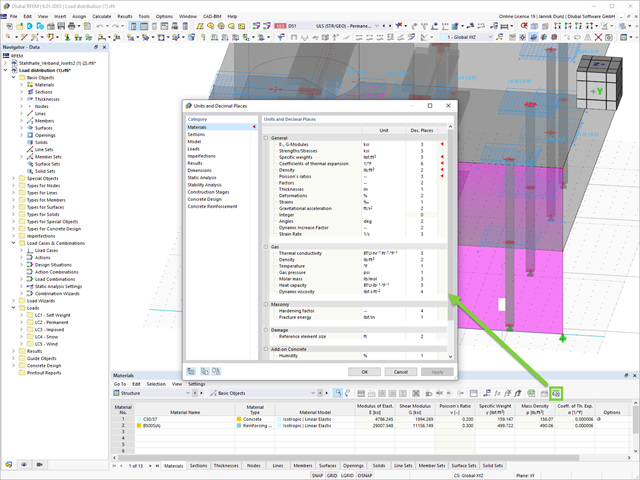
You can now change certain units in the form of a tabular user interface. You can now change certain units in the form of a tabular user interface.

- Calculation of stationary incompressible turbulent wind flow using the SimpleFOAM solver from the OpenFOAM® software package
- Numerical scheme according to the first and second order
- Turbulence models RAS k-ω and RAS k-ε
- Consideration of surface roughness depending on model zones
- Model design via VTP, STL, OBJ, and IFC files
- Operation via bidirectional interface of RFEM or RSTAB for importing model geometries with standard-based wind loads and exporting wind load cases with probe-based printout report tables
- Intuitive model changes via drag & drop and graphical adjustment assistance
- Generation of a shrink-wrap mesh envelope around the model geometry
- Consideration of environmental objects (buildings, terrain, and so on)
- Height-dependent description of the wind load (wind speed and turbulence intensity)
- Automatic meshing depending on a selected depth of detail
- Consideration of layer meshes near the model surfaces
- Parallelized calculation with optimal utilization of all processor cores of a computer
- Graphical output of the surface results on the model surfaces (surface pressure, Cp coefficients)
- Graphical output of the flow field and vector results (pressure field, velocity field, turbulence – k-ω field, and turbulence – k-ε field, velocity vectors) on Clipper/Slicer planes
- Display of 3D wind flow via animated streamline graphics
- Definition of point and line probes
- Multilingual user interface (German, English, Czech, Spanish, French, Italian, Polish, Portuguese, Russian, and Chinese)
- Calculations of several models in one batch process
- Generator for creating rotated models to simulate different wind directions
- Optional interruption and continuation of the calculation
- Individual color panel per result graphic
- Display of diagrams with separate output of results on both sides of a surface
- Output of the dimensionless wall distance y+ in the mesh inspector details for the simplified model mesh
- Determination of the shear stress on the model surface from the flow around the model
- Calculation with an alternative convergence criterion (you can select between the residual types pressure or flow resistance in the simulation parameters)

To model structures in RWIND Basic, you find a special application in RFEM and RSTAB. Here, you define the wind directions to be analyzed by means of related angular positions about the vertical model axis. At the same time, you define the elevation-dependent wind profile on the basis of a wind standard. In addition to these specifications, you can use the stored calculation parameters to determine your own load cases for a stationary calculation per each angular position.
As an alternative, you can also use the RWIND Basic program manually, without the interface application in RFEM or RSTAB. In this case, RWIND Basic models the structures and terrain environment directly from the imported VTP, STL, OBJ, and IFC files. You can define the height-dependent wind load and other fluid-mechanical data directly in RWIND Basic.
.jpg?mw=640&hash=81d73d5501397b910013fb09e66e758eaa32bd62)
There are also improvements in the data exchange to make your work process easier. In addition to the import of IFC 2x3 (Coordination View & Structural Analysis View), the import and export of IFC 4 (Reference View & Structural Analysis View) is now supported.
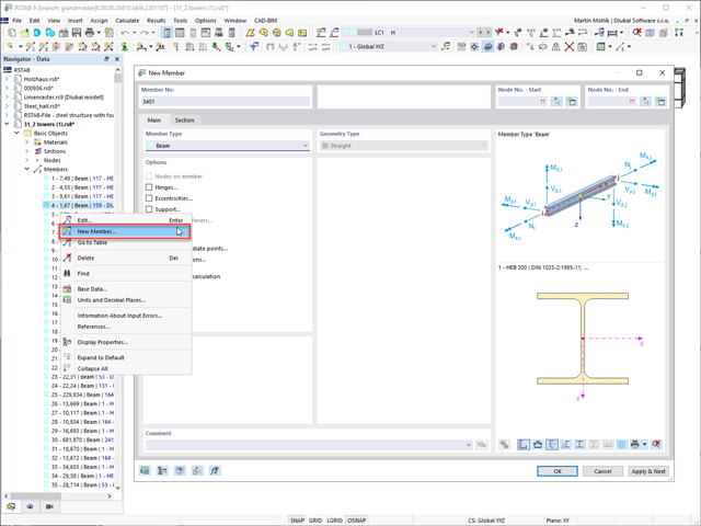
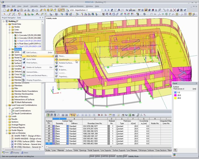
You create your models in the graphical user interface typical for CAD programs. By right-clicking the graphical or navigator objects, you activate a shortcut menu that you can use to select and modify the objects.
The operation of the user interface is intuitive, as you will notice soon. Therefore, you can create the structural and loading objects in a minimum amount of time.
Go to Explanatory Video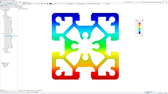
- Extensive library of rolled, parametric thin-walled and thick-walled cross-sections
- Extensible library for material properties
- Import of dxf files
- Cross-section properties of thin-walled or thick-walled cross-sections
- Ideal section properties of cross-sections consisting of different materials
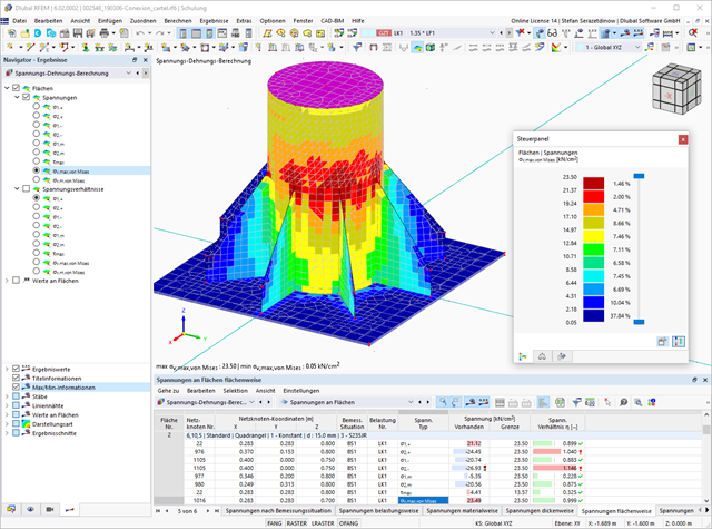
- Stress analysis
- Plastic capacity design with interaction of internal forces according to the Simplex Method
- Design of reinforcement and the subsequent design of concrete cross-section in the Concrete Design add-on (see Product Feature)
- Saving cross-sections as a block
- Scripting with JavaScript
- Interface with MS Excel for exporting tables
- Connection to Webservice & API (for example, optional creation of cross-section and access to result tables)
- Printout report
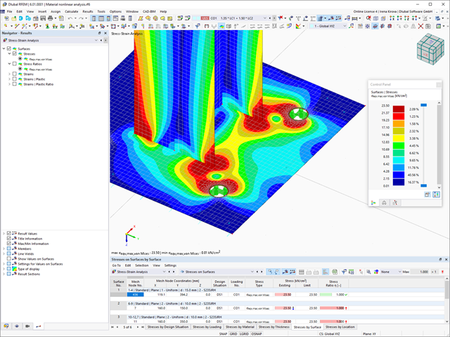
Did you know? When unloading the structural component with a plastic material model, in contrast to the Isotropic | Nonlinear Elastic material model, the strain remains after it has been completely unloaded.
You can select three different definition types:
- Standard (definition of the equivalent stress under which the material plastifies)
- Bilinear (definition of the equivalent stress and strain hardening modulus)
- Stress-strain diagram: definition of polygonal stress-strain diagram
- Option to save / import the diagram
- Interface with MS Excel
If you release a structural component with a nonlinear elastic material again, the strain goes back on the same path. In contrast to the Isotropic|Plastic material model, there is no strain left when completely unloaded.
You can select three different definition types:
- Standard (definition of the equivalent stress under which the material plastifies)
- Bilinear (definition of the equivalent stress and strain hardening modulus)
- Stress-Strain Diagram:
- Definition of polygonal stress-strain diagram
- Option to save / import the diagram
- Interface with MS Excel
Background information about nonlinear material models can be found in the technical article describing the yield laws in isotropic nonlinear elastic material model.

- You can activate or deactivate the use of torsional warping in the Add-ons tab of the model's Base Data.
- After activating the add-on, the user interface in RFEM is extended by some new entries in the navigator, tables, and dialog boxes.
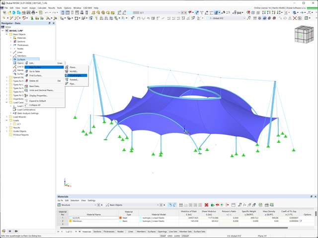
A great strength of the Dlubal programs is their intuitive, easy-to-learn operation. RFEM 6 is no exception. Create your structure in a user interface usual for CAD or via tables. By right-clicking the graphical or navigator objects, a shortcut menu appears, which facilitates you creating or editing the objects. Due to the intuitive user interface, you can create structural and loading objects in a very short time.
Go to Explanatory Video.png?mw=640&hash=9a883491884955dbc811b6573882f2d9b2702a99)
The RWIND Simulation program for generating wind loads based on CFD can be utilized in different languages; for example, in:
- German
- English
- Czech
- Spanish
- French
- Italian
- Polish
- Portuguese
- Russian
- 3D incompressible wind flow analysis with OpenFOAM® software package
- Direct model import from RFEM or RSTAB including neighboring and terrain models (3DS, IFC, STEP files)
- Model design via STL or VTP files independent of RFEM or RSTAB
- Simple model changes using Drag and Drop and graphical adjustment assistance
- Automatic corrections of the model topology with shrink wrap networks
- Option to add objects from the environment (buildings, terrain ...)
- Wind load determined over the height of the building, depending on standard-specific parameters (velocity, turbulence intensity)
- K-epsilon and K-omega turbulence models
- Automatic mesh generation adjusted to the selected depth of detail
- Parallel calculation with optimal utilization of the capacity of multicore computers
- Results in just minutes for low-resolution simulations (up to 1 million cells)
- Results within a few hours for simulations with medium/high resolution (1‑10 million cells)
- Graphical display of results on the Clipper/Slicer planes (scalar and vector fields)
- Graphical display of streamlines
- Streamline animation (optional video creation)
- Definition of point and line probes
- Display of aerodynamic pressure coefficients
- Graphical display of turbulence properties in the wind field
- Optional meshing using the boundary layer option for the area near the model surface
- Consideration of rough model surfaces possible
- Optional use of a seond-order numerical Order
- Multilingual user interface (for example, German, English, Spanish, French)
- Documentation possible in the RFEM and RSTAB printout report
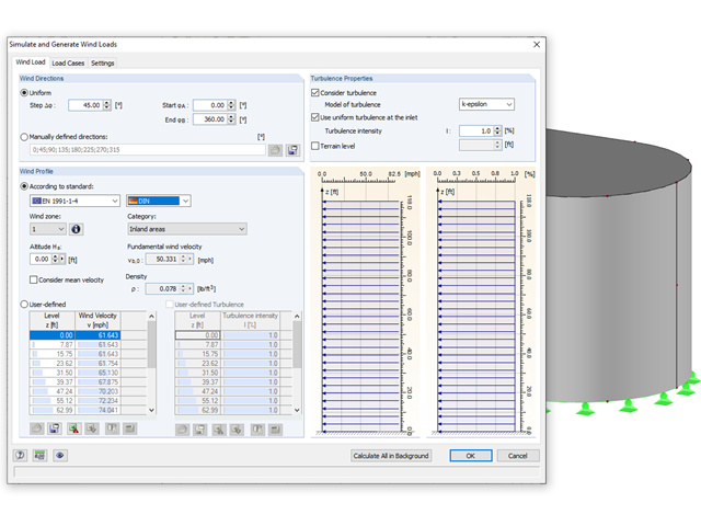
Rely on the Dlubal programs even in windy matters. RFEM and RSTAB provide a special interface for exporting models (that is, structures defined by members and surfaces) to RWIND 2. There, the wind directions to be analyzed for your project are defined by means of related angular positions about the vertical model axis. Furthermore, the elevation-dependent wind profile and turbulence intensity profile are defined on the basis of a wind standard. These specifications result in specific load cases, depending on the angle. For this, the fluid parameters, turbulence model properties, and iteration parameters that are all stored globally are helpful. You can extend these load cases by partial editing in the RWIND 2 environment using terrain or environment models from STL vector graphics.
As an alternative, you can also run RWIND 2 manually and without the interface application in RFEM or RSTAB. In this case, the structures and terrain environment in the program are directly modeled by imported STL and VTP files. You can define the height-dependent wind load and other fluid-mechanical data directly in RWIND 2.
Due to its versatile applicability, RWIND 2 is always at your side to support you in your individual projects.
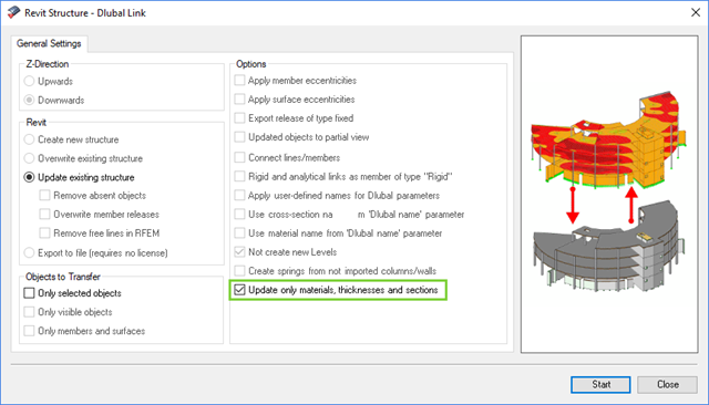
The direct interface with Revit allows you to update the Revit model according to the changes you have made in RFEM or RSTAB. Depending on the modification, the Revit objects may have to be regenerated (deleting the object and subsequent regeneration). The regeneration is performed on the basis of the RFEM/RSTAB model.
If you want to avoid this regeneration, activate the check box 'Update only materials, thicknesses, and sections'. In this case, only the properties of the objects will be adjusted. Changes different from those in material, surface thickness, and section are, however, not considered in this case.
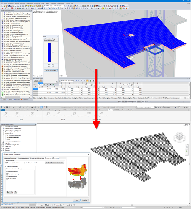
Surface reinforcements defined in the RF-CONCRETE Surfaces add-on module can be exported to Revit as reinforcement objects via the direct interface. To do this, you can optionally select surface, rectangular, polygon, and circular reinforcement areas in RF-CONCRETE Surfaces. In addition to bar reinforcement, it is possible to export mesh reinforcement.
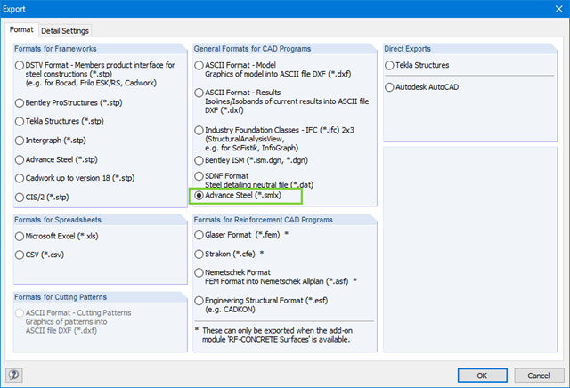
When exchanging data with Advance Steel using *.smlx files, the interface is detected automatically. This means that *.smlx files can be created even if no version of Advance Steel is installed.
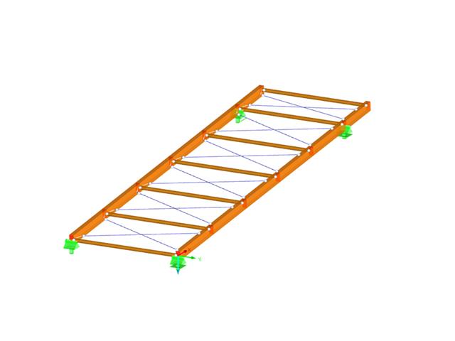
- Design of the following roof types:
- Monopitch roof
- Duopitch Roof
- Curved roof
- All roof shapes allow for a free selection of stiffening diagonals. The following types are available:
- Falling diagonals
- Rising diagonals
- Crossing diagonals with verticals
- Crossing diagonals without verticals
- Crossing diagonals with steel strips (ties)
- Consideration of window rows in the ridge by selecting an inner intermediate part.
- For design according to EC 5 (EN 1995), the following National Annexes are available:
-
 DIN EN 1995-1-1/NA:2013-08 (Germany)
 -
 NBN EN 1995-1-1/ANB:2012-07 (Belgium)
 -
 DK EN 1995-1-1/NA:2011-12 (Denmark)
 -
 SFS EN 1995-1-1/NA:2007-11 (Finland)
 -
 NF EN 1995-1-1/NA:2010-05 (France)
 -
 UNI EN 1995-1-1/NA:2010-09 (Italy)
 -
 NEN EN 1995-1-1/NB:2007-11 (Netherlands)
 -
 ÖNORM B 1995-1-1:2015-06 (Austria)
 -
 PN EN 1995-1-1/NA:2010-09 (Poland)
 -
 SS EN 1995-1-1 (Sweden)
 -
 STN EN 1995-1-1/NA:2008-12 (Slovakia)
 -
 SIST EN 1995-1-1/A101:2006-03 (Slovenia)
 -
 CSN EN 1995-1-1:2007-09 (Czech Republic)
 -
 BS EN 1995-1-1/NA:2009-10 (the United Kingdom)
-
- Simple geometry input with illustrative graphics
- Automatic generation of wind loads
- Automatic creation of required combinations for the ultimate and serviceability limit states, as well as fire resistance design
- Free definition of the load cases to be used
- Extensive material library
- Optional extension of material library by further materials
- Extensive library of permanent loads
- Allocation of framework to service classes and specification of service class categories
- Determination of design ratios, support forces, and deformations
- Info icon indicating successful or failed design
- Color reference scales in result tables
- Direct data export to MS Excel
- DXF interface for preparation production documents in CAD
- Program languages: English, German, Czech, Italian, Spanish, French, Portuguese, Polish, Chinese, Dutch, and Russian
- Verifiable printout report, including all required designs. Printout report available in many output languages; for example, English, German, French, Italian, Spanish, Russian, Czech, Polish, Portuguese, Chinese, and Dutch.
- In the ultimate limit state design, the stiffness of the hinge is divided by the partial safety factor and in the serviceability limit state design calculated using the mean stiffnesses. The limit values for the ultimate and the serviceability limit states can be defined separately.
- Design of the following geometrical types:
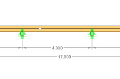
- Single-span beams with and without cantilevers
- Continuous beams with and without cantilevers
- Hinged girder system (Gerber beams) with and without cantilevers
- For design according to EC 5 (EN 1995), the following National Annexes are available:
-
DIN EN 1995-1-1/NA:2013-08 (Germany)
-
NBN EN 1995-1-1/ANB:2012-07 (Belgium)
-
DK EN 1995-1-1/NA:2011-12 (Denmark)
-
SFS EN 1995-1-1/NA:2007-11 (Finland)
-
NF EN 1995-1-1/NA:2010-05 (France)
-
UNI EN 1995-1-1/NA:2010-09 (Italy)
-
NEN EN 1995-1-1/NB:2007-11 (Netherlands)
-
ÖNORM B 1995-1-1:2015-06 (Austria)
-
PN EN 1995-1-1/NA:2010-09 (Poland)
-
SS EN 1995-1-1 (Sweden)
-
STN EN 1995-1-1/NA:2008-12 (Slovakia)
-
SIST EN 1995-1-1/A101:2006-03 (Slovenia)
-
CSN EN 1995-1-1:2007-09 (Czech Republic)
-
BS EN 1995-1-1/NA:2009-10 (the United Kingdom)
-
- Automatic generation of wind and snow loads
- Multiple optional reductions according to the selected standard
- Simple geometry input with illustrative graphics
- Free entry of tapered geometries. Free selection of the grain angle allows for user-defined design of the compressive and tensile areas for bending
- Comprehensive and extensible material library
- Determination of design ratios, support forces, and deformations
- Color reference scales in result tables
- Direct data export to MS Excel
- DXF interface for preparation production documents in CAD
- Program languages: English, German, Czech, Italian, Spanish, French, Portuguese, Polish, Chinese, Dutch, and Russian
- Verifiable printout report, including all required designs. Printout report available in many output languages; for example, English, German, French, Italian, Spanish, Russian, Czech, Polish, Portuguese, Chinese, and Dutch.
- Direct import of stp files from various CAD programs
Dlubal Software customers come from all over the world and there are, of course, numerous language options for the structural analysis software. It is possible to operate the program in the following languages: English, Chinese, Czech, Dutch, French, German, Italian, Polish, Portuguese, Russian, and Spanish.
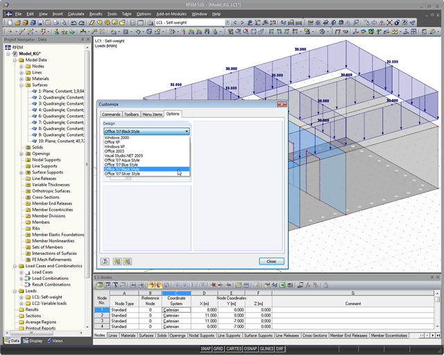
You can also modify the design of the RFEM/RSTAB user interface: There are nine different styles of graphical user interface to choose from; for example: Office 2007 Blue, Silver, Aqua, and Black. Customize the programs to your individual needs.
The Dlubal programs are user-friendly. This way, you will have a short induction period and easy handling of the software.
Your structure is created in a user interface usual for CAD or via tables. By right-clicking the graphical or navigator objects, you can activate a shortcut menu that allows you to easily create or modify the objects. Try it out for yourself and let yourself be inspired by the intuitive user interface! Therefore, you can create the structural and loading objects in a minimum amount of time.

- Modeling of the cross-section via elements, sections, arcs, and point elements
- Expansible library of material properties, yield strengths, and limit stresses
- Section properties of open, closed, or non-connected cross-sections
- Ideal section properties of cross-sections consisting of different materials
- Determination of weld stresses in fillet welds
- Stress analysis including design of primary and secondary torsion
- Check of c/t-ratios
- Effective cross-sections according to
- EN 1993-1-5 (including stiffened buckling panels according to Section 4.5)
-
 EN 1993-1-3
 -
EN 1999-1-1
-
to DIN 18800-2
- Classification according to
-
EN 1993-1-1
-
EN 1999-1-1
-
- Interface with MS Excel to import and export tables
- Printout report
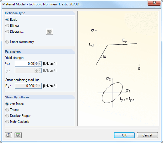
The following material models are available in RF − MAT NL:
Isotropic Plastic 1D/2D/3D and Isotropic Nonlinear Elastic 1D/2D/3D
You can select three different definition types here:
- Basic (definition of the equivalent stress under which the material plastifies)
- Bilinear (definition of the equivalent stress and strain hardening modulus)
- Diagram:
- Definition of polygonal stress-strain diagram
- Option to save / import the diagram
- Interface with MS Excel
Orthotropic Plastic 2D/3D (Tsai-Wu 2D/3D)
This material model allows the definition of material properties (modulus of elasticity, shear modulus, Poisson's ratio) and ultimate strengths (tension, compression, shear) in two or three axes.
Isotropic Masonry 2D
It is possible to specify the limit tension stresses σx,limit and σy,limit as well as the hardening factor CH.
Orthotropic Masonry 2D
The material model Orthotropic Masonry 2D is an elastoplastic model that additionally allows softening of the material, which can be different in the local x- and y-directions of a surface. The material model is suitable for (unreinforced) masonry walls with in-plane loads.
Isotropic Damage 2D/3D
Here, you can define antimetric stress-strain diagrams. The modulus of elasticity is calculated in each step of the stress-strain diagram using Ei = (σi -σi-1 )/(εi -εi-1 ).
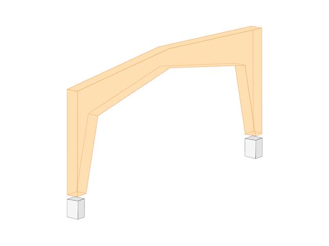
- Design of the following geometrical types:
- Symmetrical / asymmetrical
- Half-frame
- Column sloping inside / outside
- Intermediate piece with / without
- Direction of lamellas can be defined as parallel to inner or outer edge
- For design according to EC 5 (EN 1995), the following National Annexes are available:
-
DIN EN 1995-1-1/NA:2013-08 (Germany)
-
NBN EN 1995-1-1/ANB:2012-07 (Belgium)
-
DK EN 1995-1-1/NA:2011-12 (Denmark)
-
SFS EN 1995-1-1/NA:2007-11 (Finland)
-
NF EN 1995-1-1/NA:2010-05 (France)
-
UNI EN 1995-1-1/NA:2010-09 (Italy)
-
NEN EN 1995-1-1/NB:2007-11 (Netherlands)
-
ÖNORM B 1995-1-1:2015-06 (Austria)
-
PN EN 1995-1-1/NA:2010-09 (Poland)
-
SS EN 1995-1-1 (Sweden)
-
STN EN 1995-1-1/NA:2008-12 (Slovakia)
-
SIST EN 1995-1-1/A101:2006-03 (Slovenia)
-
CSN EN 1995-1-1:2007-09 (Czech Republic)
-
BS EN 1995-1-1/NA:2009-10 (the United Kingdom)
-
- Simple geometry input with illustrative graphics
- Automatic generation of wind and snow loads
- Automatic creation of required combinations for the ultimate and serviceability limit states, as well as fire resistance design
- Possibility to define load cases and load applications
- Extensive material library for both standards
- Optional extension of material library by further materials
- Extensive library of permanent loads
- Allocation of framework to service classes and specification of service class categories
- Determination of design ratios, support forces, and deformations
- Info icon indicating successful or failed design
- Color reference scales in result tables
- Direct data export to MS Excel
- DXF interface for preparation production documents in CAD
- Program languages: English, German, Czech, Italian, Spanish, French, Portuguese, Polish, Chinese, Dutch, and Russian
- Verifiable printout report, including all required designs. Printout report available in many output languages; for example, English, German, French, Italian, Spanish, Russian, Czech, Polish, Portuguese, Chinese, and Dutch.
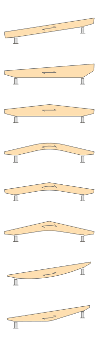
- Design of the following beam types:
- Parallel beam
- Monopitch roof beam
- Double tapered beam
- Arched beam
- Pitched cambered beam with constant height
- Pitched cambered beam with variable height
- Fish Beam - Parabolic
- Fish beam - Linear with rounding in central area
- Unsymmetrical beams with and without cantilevers
- Arrangement of a loose ridge wedge
- Optional consideration of stiffening elements for transversal tension
- Two design types available for stiffening elements concerning transversal tension:
- Constructive if required
- Full absorption of tension stresses perpendicular to grain
- Calculation of required number of stiffening elements for transversal tension and graphical representation of the arrangement in the beam
- Simple geometry input with illustrative graphics
- Convenient generation of snow loads according to EN 1991-1-3 or DIN 1055:2005, Part 5
- Automatic determination of wind loads according to EN 1991-1-4 or DIN 1055:2005, Part 4
- User-defined load cases and load applications
- Automatic generation of all possible load combinations
- Connection to MS Excel and access via COM interface
- Material library for both standards
- For design according to EC 5 (EN 1995), the following National Annexes are available:
-
DIN EN 1995-1-1/NA:2013-08 (Germany)
-
NBN EN 1995-1-1/ANB:2012-07 (Belgium)
-
DK EN 1995-1-1/NA:2011-12 (Denmark)
-
SFS EN 1995-1-1/NA:2007-11 (Finland)
-
NF EN 1995-1-1/NA:2010-05 (France)
-
UNI EN 1995-1-1/NA:2010-09 (Italy)
-
NEN EN 1995-1-1/NB:2007-11 (Netherlands)
-
ÖNORM B 1995-1-1:2015-06 (Austria)
-
PN EN 1995-1-1/NA:2010-09 (Poland)
-
SS EN 1995-1-1 (Sweden)
-
STN EN 1995-1-1/NA:2008-12 (Slovakia)
-
SIST EN 1995-1-1/A101:2006-03 (Slovenia)
-
CSN EN 1995-1-1:2007-09 (Czech Republic)
-
BS EN 1995-1-1/NA:2009-10 (the United Kingdom)
-
- Extensive library of permanent loads
- Allocation of a structure to service class, and specification of service class categories
- Determination of design ratios, support forces, and deformations
- Info icon indicating successful or failed design
- Color reference scales in result tables
- Direct data export to MS Excel
- DXF interface for preparation production documents in CAD
- Program languages: English, German, Czech, Italian, Spanish, French, Portuguese, Polish, Chinese, Dutch, and Russian
- Verifiable printout report, including all required designs. Printout report available in many output languages; for example, English, German, French, Italian, Spanish, Russian, Czech, Polish, Portuguese, Chinese, and Dutch.
When determining internal forces, you can choose between calculation method 1 (uncracked over entire beam length) and calculation method 2 (crack formation over internal columns).
In both cases, it is possible to consider a constant effective width of the concrete slab over the entire span according to ENV 1994-1-1, 4.2.2.1 (1) and a redistribution of the moments. Internal forces for the design of shear connectors can only be determined by the elastic calculation of internal forces using the RSTAB analysis core (no RSTAB license is required).
The calculation performs fully automatic determination of the effective cross-section properties at the respective points of time, considering creep and shrinkage. In the RSTAB user interface, the structural models are created as a member structure, including all boundary conditions and loading. This way, reliable calculation of the internal forces with the effective cross-section properties is ensured.